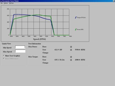
My Car is on the DYNO right now. So far...

TRBOBUICK said:
Dynos are funny. Mine went on right after dans. My car wouldnt build much more than 12, but on the street 25 was on tap. Im sure dans car is going to fly.
CONGRATS DAN !!!


Does that have something to do with how much load the dyno is putting on the rear tires?
 
Im not sure. Sean had the load cranked up on both of our cars. Important thing is the 02's are commanded for a safe a/f and thats what counts. Sean is going to help me with some track tuning.
 
orangejuiced86 said:
Does that have something to do with how much load the dyno is putting on the rear tires?

I am still mistified by brians lack of boost building on the dyno. Dans car seems not to have that trouble however. Here is Dans Dyno sheet since i was asked to post it.

Sean
 

Attachments

  • Dan Mcgee.JPG
    Dan Mcgee.JPG
    57.3 KB · Views: 150
robh said:
Congrats Dan, Sounds like your a sold turbo addict. Does it feel like a manual turbo diesel?

I like to see the numbers you and Raj came up with on the turbo sizing sometime. I was just wondering if the car wouldn't build boost on the dyno but is able to on the street.

Another turbo mustang running...just awesome...


Rob,

That's a good way to describe the power curve on this thing - like a turbo diesel. It hits hard and quick and just seems to keep pulling. I was experimenting a little bit at my super-secret, late-night, dragrace spot and the car seems to go faster as I short-shift the thing, sorta like a diesel truck!

Give me a call and I'll walk you through the math that Raj and I were talking about - 734.968.3570

Dan
 
dpmcghee said:
Rob,

That's a good way to describe the power curve on this thing - like a turbo diesel. It hits hard and quick and just seems to keep pulling. I was experimenting a little bit at my super-secret, late-night, dragrace spot and the car seems to go faster as I short-shift the thing, sorta like a diesel truck!

Give me a call and I'll walk you through the math that Raj and I were talking about - 734.968.3570

Dan

Dan PM that place. Maybe the Trunk and I met you there.
 
robh said:
Congrats Dan, Sounds like your a sold turbo addict. Does it feel like a manual turbo diesel?

I like to see the numbers you and Raj came up with on the turbo sizing sometime. I was just wondering if the car wouldn't build boost on the dyno but is able to on the street.

Another turbo mustang running...just awesome...

hp per cube and total airflow avialable say nope 90 lb/min. the Compressor is looking like its out of air. We never did see the waste gate open. the TQ is there to make close to 800hp but the RPM for the TQ curve is really low. Retarding the camhsaft 6-8 degree might move it upstairs enough to bring the top end power out. the total flow of the compressor given optimal conditions is 90lbs minute. divide like so

90 lb minute ( flow ) /.0807 ( wieght of cubic foot of air )

90/0.0807 = 1115.24 cfm


the TQ is there to support the engine using all of the aviable flow IMO. From what Ive seen over the years about 2cfm per ft lb is fairly normal. ive seen it as efficient as 1.75cfm pr ft lb and as bad as 2.25 but either way its middle of the road. given the bore stroke combination head flow and the ever critical runner length the TQ curve make sense to me.

I think the most important thing to note is power under the curve. This car makes literally gobs of power under the curve and If it were drag racing id shift it at 5600-5800rpm. it doesn't exhibit any of the normal problems seen with turbo cars like peaky power output. the turbo come on hard at around 3500rpm and stays on till around 5800rpm. nice wide power curve the car should hual some serious ass.
 
Sean,
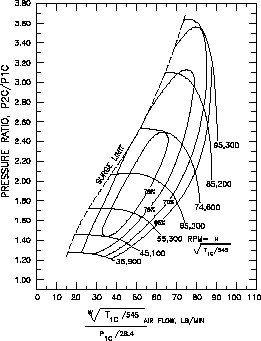
Thanks for posting some of the info. I'm not completely familiar with his combo i.e. c.i., heads but I thought he was running a t76.

I didn't quite understand your formula as I always use these for my own stuff:

(CID X RPM) / 3456 =CFM

CFM = (CID X RPM) / 3456 X VE

Assuming VE to be around 85%

CFM X .069 = LBS/MIN

I don't claim to be an expert as I only read the Turbocharging guide by Spencer Brown. I also don't want to post all of Dan's set up info on here either. Good luck to Dan in search for more boost!!!
 

Attachments

  • t76.jpg
    t76.jpg
    28.2 KB · Views: 98
Last edited:
I would imagine that your car should put down more boost than that. The dyno probly did not just load the motor enough.

That in turn will not get the turbo spooling.

You sould be right around 8-900 hp maxed out wtih a 76 with the combo you have mentiond....
 
What an awesome combo! I want a torque curve like that in my Z28. That thing must be a blast to drive!

-Geoff
 
1slow305 said:
I would imagine that your car should put down more boost than that. The dyno probly did not just load the motor enough.

That in turn will not get the turbo spooling.

You sould be right around 8-900 hp maxed out wtih a 76 with the combo you have mentiond....

Dont get hung up on dyno numbers. A t-76 will never support 900 at the tires.
 
robh said:
Sean,
Thanks for posting some of the info. I'm not completely familiar with his combo i.e. c.i., heads but I thought he was running a t76.

I didn't quite understand your formula as I always use these for my own stuff:

(CID X RPM) / 3456 =CFM

CFM = (CID X RPM) / 3456 X VE

Assuming VE to be around 85%

CFM X .069 = LBS/MIN

I don't claim to be an expert as I only read the Turbocharging guide by Spencer Brown. I also don't want to post all of Dan's set up info on here either. Good luck to Dan in search for more boost!!!

VE means nothing in turbo world. While its a good estimator its not the end all be all . the problem all the formulas run into is that only predict CFM for HP vs RPM not for airflow required to make a given amount of TQ. I will see if i can put the Mathmatical mdel together in what ittle spare time I've got. Migt be a few days, Rule of thumb is 2cfm per FT LB though

here is an interesting formula i found surinfg the net,

HP / 0.257 / cylinders = required airflow
we are shooting for 750hp

750/ 0.257 = 2918 cfm but that is going to depend on the TQ peak and peak rp, for hp.

HP formula is TQ x RPM / 5250 + HP

In the case of Dans car we have 632lb ft x 6200 RPM = 746hp.

Even using the most basic of calculations its fiarly obvious that the t76 is out of air regardless of the engine design.the only way to make 750hp with this particular turbo is to put it on a smaller engine and rev the snot out of it but it will still fall short.
 
Last edited:
robh said:
Sean,
Thanks for posting some of the info. I'm not completely familiar with his combo i.e. c.i., heads but I thought he was running a t76.

I didn't quite understand your formula as I always use these for my own stuff:

(CID X RPM) / 3456 =CFM

CFM = (CID X RPM) / 3456 X VE

Assuming VE to be around 85%

CFM X .069 = LBS/MIN

I don't claim to be an expert as I only read the Turbocharging guide by Spencer Brown. I also don't want to post all of Dan's set up info on here either. Good luck to Dan in search for more boost!!!


wow your CMF to lbs/minute number is very far off. should be CFM x 0.0807 to get lbs/min. CFM from pounds per minute lbs min/0.0807
 
Last edited:
8URZ0H6 said:
Hey Dan,

Is this a T76 Q-Trim?


That would be the one... .96A/R on the hot side.

The problem is that I don't understand all this math when it comes to turbos, engine consumption, etc...

The other thing that I just don't understand is that if you go to www.turbomustangs.com and go to their dyno section (where people post their results from dyno sessions) there are quite a few people using this turbo on similar combos, and they are making upwards of 800hp and in some cases have even cracked the 900rwhp mark running 20+ lbs of boost.

Dan
 
Last edited:
dpmcghee said:
The other thing that I just don't understand is that if you go to www.turbomustangs.com and go to their dyno section (where people post their results from dyno sessions) there are quite a few people using this turbo on similar combos, and they are making upwards of 800hp and in some cases have even cracked the 900rwhp mark running 20+ lbs of boost.

Dan

Exactly.
I have never heard of a combo that couldn't make boost. I have seen overboosting to compensate for the turbo being to small taking the turbo out of the efficientcy range.

Dan,
I would read this for yourself and run through the calculations that way you can make the best decisions for your combo.

http://www.turbomustangs.com/turbotech/main.htm#selectcompressor
 
Compressor Selection
When using the formula's below, you will need to use compressor flow maps and work with the formulas until you size the compressor that will work for your application. Compressor flow maps are available from the manufacturer, do a search on the web, or use the maps I have provided. On the flow maps, the airflow requirements should fall somewhere between the surge line and the 60% efficiency line, the goal should be to get in the peak efficiency range at the point of your power peak. In this article I will walk through an example as I explain it.
Engine Airflow Requirements
In order to select a turbocharger, you must know how much air it must flow to reach your goal. You first need to figure the cubic feet per minute of air flowing through the engine at maximum rpm. The the formula to to this for a 4 stroke engine is:

(CID × RPM) ÷3456 = CFM

For a 2 stroke you divide by 1728 rather than 3456. Lets assume that you are turbocharging a 302 cubic inch engine That will redline at 6000 rpm.

(302 × 6000) ÷ 3456 = 524.3 CFM

The engine will flow 524.3 CFM of air assuming a 100% volumetric efficiency. Most street engines will have an 80-90% VE, so the CFM will need to be adjusted. Lets assume our 302 has an 85% VE.

524.3 × 0.85 = 445.7 CFM
Our 302 will actually flow 445.7 CFM with an 85% VE.
Pressure Ratio
The pressure ratio is simply the pressure in, compared to the pressure out of the turbocharger. The pressure in is usually atmospheric pressure, but may be slightly lower if the intake system before the turbo is restrictive, the inlet pressure could be higher than atmospheric if there is more than 1 turbocharger in series. In that case the inlet let pressure will be the outlet pressure of the turbo before it. If we want 10 psi of boost with atmospheric pressure as the inlet pressure, the formula would look like this:

(10 + 14.7) ÷ 14.7 = 1.68:1 pressure ratio

Temperature Rise
A compressor will raise the temperature of air as it compresses it. As temperature increases, the volume of air also increases. There is an ideal temperature rise which is a temperature rise equivalent to the amount of work that it takes to compress the air. The formula to figure the ideal outlet temperature is:

T2 = T1 (P2 ÷ P1)0.283

Where:
T2 = Outlet Temperature °R
T1 = Inlet Temperature °R
°R = °F + 460
P1 = Inlet Pressure Absolute
P2 = Outlet Pressure Absolute

Lets assume that the inlet temperature is 75° F and we're going to want 10 psi of boost pressure. To figure T1 in °R, you will do this:

T1 = 75 + 460 = 535°R

The P1 inlet pressure will be atmospheric in our case and the P2 outlet pressure will be 10 psi above atmospheric. Atmospheric pressure is 14.7 psi, so the inlet pressure will be 14.7 psi, to figure the outlet pressure add the boost pressure to the inlet pressure.

P2 = 14.7 + 10 = 24.7 psi

For our example, we now have everything we need to figure out the ideal outlet temperature. We must plug this info into out formula to figure out T2:

T1 = 75
P1 = 14.7
P2 = 24.7

The formula will now look like this:

T2 = 535 (24.7 ÷ 14.7)0.283 = 620 °R

You then need to subtract 460 to get °F, so simply do this:

620 - 460 = 160 °F Ideal Outlet Temperature

This is a temperature rise of 85 °F

Adiabatic Efficiency
The above formula assumes a 100% adiabatic efficiency (AE), no loss or gain of heat. The actual temperature rise will certainly be higher than that. How much higher will depend on the adiabatic efficiency of the compressor, usually 60-75%. To figure the actual outlet temperature, you need this formula:

Ideal Outlet Temperature Rise ÷ AE = Actual Outlet Temperature Rise

Lets assume the compressor we are looking at has a 70% adiabatic efficiency at the pressure ratio and flow range we're dealing with. The outlet temperature will then be 30% higher than ideal. So at 70% it using our example, we'd need to do this:

85 ÷ 0.7 = 121 °F Actual Outlet Temperature Rise

Now we must add the temperature rise to the inlet temperature:

75 + 121 = 196 °F Actual Outlet Temperature
Density Ratio
As air is heated it expands and becomes less dense. This makes an increase in volume and flow. To compare the inlet to outlet air flow, you must know the density ratio. To figure out this ratio, use this formula:

(Inlet °R ÷ Outlet °R) × (Outlet Pressure ÷ Inlet Pressure) = Density Ratio

We have everything we need to figure this out. For our 302 example the formula will look like this:

(535 ÷ 656) × (24.7 ÷ 14.7) = 1.37 Density Ratio

Compressor Inlet Airflow
Using all the above information, you can figure out what the actual inlet flow in in CFM. Do do this, use this formula:

Outlet CFM × Density Ratio = Actual Inlet CFM

Using the same 302 in our examples, it would look like this:

447.5 CFM × 1.37 = 610.6 CFM Inlet Air Flow

That is about a 37% increase in airflow and the potential for 37% more power. When comparing to a compressor flow map that is in Pounds per Minute (lbs/min), multiply CFM by 0.069 to convert CFM to lbs/min.

610.6 CFM × 0.069 = 42.1 lbs/min

Now you can use these formula's along with flow maps to select a compressor to match your engine. You should play with a few adiabatic efficiency numbers and pressure ratios to get good results. For twin turbo's, remember that each turbo will only flow 1/2 the total airflow.

Using Your Numbers
A turbocharger compressor map has two axis. On the x-axis (the horizontal one) is the airflow, often in lbs/minute. On the y-axis is the pressure ratio, usually as "1+boost pressure", in bar. Inside the map there are plots for turbine rpm, more or less horizontal lines, efficiency (oval rings) and most often also surge limit - a dotted line.

To use the map, you need to know the airflow you will have through the engine.

Using this value, you can use a map. Draw a line from your air flow (lbs/min) on the x-axis, and a line from the pressure ratio (psi + 14.7 ÷14.7 ). The point of intersection will hopefully be inside one of the higher efficiency rings, about 70%.

You should always have the intersection to the right of the surge limit, otherwise it is no good.

The way to do this is to plot 5-10 intersections (different rpms and boost pressures) in different maps. By having maps for different turbos, and trying different boost pressures and rpm, you can get an idea of how it’s going to work.

Remember this only gives an estimate, you might have to resort to trial and error to get exactly spot on. This way, however, you can be reasonably sure you are in the right ballpark.

1 bar = 14.50377 PSI

1 PSI = 0.06894757 bar
 
Remember though, more cubes, better flowing heads and intake, and the psi wont build. Raj had trouble making more than 22 psi last year, i have a smaller engine and peanut port heads and found out last year that the same turbo will make 30+ .

I guess it all boils down to this: if dans mustang runs mid/bottom nines, who cares what the dyno says ?
 
dpmcghee said:
That would be the one... .96A/R on the hot side.

The problem is that I don't understand all this math when it comes to turbos, engine consumption, etc...

The other thing that I just don't understand is that if you go to www.turbomustangs.com and go to their dyno section (where people post their results from dyno sessions) there are quite a few people using this turbo on similar combos, and they are making upwards of 800hp and in some cases have even cracked the 900rwhp mark running 20+ lbs of boost.

Dan


We are focusing to much on HP and not enough on AVG TQ production. you've got TQ in Spades and the TQ if it could hold out to 6200rpm would be well north of 750hp. ALso Boost is a restriction to airflow.

Also the airflow formula Robh is using is still wrong. I grabbed this wright off of the wieghts and standards website.

FINAL ANSWER: 1 cubic foot of air at standard temperature and pressure assuming average composition weighs approximately 0.0807 lbs.
 
Last edited:
Well guys, I just pulled all eight sparkplugs and they are all fouled beyond belief - black as can be... I'm not sure why. Several of them were only finger tight as well.

Also, I changed the oil and decided to empty the oil in the catch-can which is connected to the driver side valve cover...guess what came out? Radiator fluid. Greeeeeeaaaaaatttttt.....

Its strange. There was zero radiator fluid in the pan. The oil was not milky at all. But there is definately a leak into the motor somewhere because the catch can was full of green fluid:dontknow: headgasket?


Dan
 
Back
Top