89-LX
Forum Member
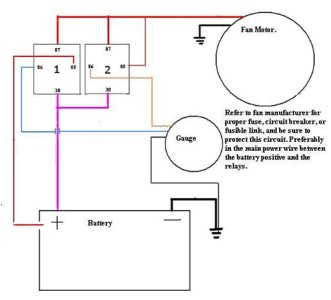
Having a small wiring issue and I hope a diode can solve this issue. Using a dual relay setup for a cooling fan as a high turn on point and low turn off point. Here is my current setup:
Relay 1 (High turn on):
30 - 12v hot power all times. Fused with a 80 amp fuse.
85 - 12v hot power all times. Fused with a 2 amp fuse.
86 - SWITCHED ground. Using this to control the flow through the relay
87 - 12v out to the cooling fan
Relay 1 (Low turn off point):
30 - 12v hot power all times. Fused with a 80 amp fuse.
85 - 12v hot from output from 87 on both relays.
86 - Controlling ground by gauge.
87 - 12v out to the cooling fan.
When the key comes out of the ignition and the controlling gauge loses its 12v switched power, the relay seems to be backfeeding power through wire 86 on relay 1. The wiring says to hook up relay 1 85 to a switched 12v source, but that shouldn't be much of a difference from hot at all times and switched. Does this mean I need to put a 1 way diode on the ground wire 86 of relay 1?
Any ideas? Thanks

